Stuck?  support@mecway.com
support@mecway.com
Mecway
FEA
Twist on beams
Hello everybody,
I ‘have been practicing with beam elements. Supporting beams of a dome roof (generated by multiple – rotation of a beam seed)
I imported the geometry but for some reason the step file do not contain the beam elements when opened with Mecway.
So I decided to solve it meshing directly outside MECWAY and importing to Mecway as unv mesh.
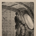
After assigning the material and section properties I have represent the real section of the beams I found that weird twist on the elements. (Attached file)
Section exaggerated to provide visibility. More twist as we are further from the seed element.
¿Any idea how to fix it?. Seems element axis have also been rotated.
By other hand the reinforcing plates do not appear as good elements. Don’t know exactly why. ¿Is there a problem in the connectivity matrix if the imported geometries or meshes do not belong all to a "unique connected body"?.
Attached reinforcing plates unv mesh too
Thanks .
I ‘have been practicing with beam elements. Supporting beams of a dome roof (generated by multiple – rotation of a beam seed)
I imported the geometry but for some reason the step file do not contain the beam elements when opened with Mecway.
So I decided to solve it meshing directly outside MECWAY and importing to Mecway as unv mesh.
After assigning the material and section properties I have represent the real section of the beams I found that weird twist on the elements. (Attached file)
Section exaggerated to provide visibility. More twist as we are further from the seed element.
¿Any idea how to fix it?. Seems element axis have also been rotated.
By other hand the reinforcing plates do not appear as good elements. Don’t know exactly why. ¿Is there a problem in the connectivity matrix if the imported geometries or meshes do not belong all to a "unique connected body"?.
Attached reinforcing plates unv mesh too
Thanks .
Howdy, Stranger!
It looks like you're new here. If you want to get involved, click one of these buttons!
Comments
Regards
I will try.
The bad element shapes are because the hex8 elements are inverted. Use Mesh tools -> Invert to correct them. They're probably inverted because Mecway is interpreting the element node numbering in the unv file differently from what you used to create it. This is a common problem with unv - the node number ordering of elements isn't well defined and different programs do it their own way. From what I've seen, Salome uses the same FE descriptor of 115 for hex8 elements that you have here but a different node ordering. Can you tell me what software you used to create it?
It's safer to use bonded contact to connect the beams to the solids rather than shells. That's because the shells don't have a drilling DOF so the joints will be pin-joints free to rotate about the shell's normal axes.
Regards
¿Any idea why I'm failing to import beam elements as a step file.?
I will try also Andreas trick.
Thanks both.